Page 45 - GarlockFluidSealing2010
SEO Version


B-13
GARFLEX
®
8100
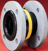
GARFLEX
®
expansion joints feature rugged yet
fexible nylon cord reinforcement in a molded, spheri-
cal bellows design that ensures an exceptional burst
pressure rating. The streamlined fowing arch design
reduces turbulence and allows smooth, quiet fow—no
need to fll the arch and restrict its movement.
Benefts
¦
Flowing arch design prevents sediment buildup and
reduces turbulence
¦
Floating fanges can be rotated to accommodate
torsional misalignment
¦
Molded spherical bellows accommodate up to one
inch of axial movement and transverse defection
¦
Nylon-reinforced nitrile tube earns high pressure rat-
ing without sacrifcing fexibility; resists most hydro-
carbons, oils and gasoline
¦
Supplied silicone-free
Design
¦
Tube
• Nitrile bellows with rugged nylon tire cord rein-
forcement ensure strength yet fexibility
• Incorporates a fowing arch design to eliminate
product buildup
¦
Cover
• Homogeneous layer of neoprene coated with a
protectant withstands weathering and ozone
¦
Flanges
• Iron fanges are corrosion-resistant
Note:
Style 8100 expansion joints are supplied with rotating fanges drilled
to ANSI Class 150# specifcations. Can be installed against raised
face pipe fanges.
Operating Temperature
Pressure
°F
°C
psi
bar
To 120°F
To 50°C
232
16
120°F to 160°F
50°C to 70°C
174
12
160°F to 195°F
70°C to 90°C
139
9.5
195°F to 210°F 90°C to 100°C
70
5
210°F to 230°F 100°C to 110°C
25
1.7
Temperature / Pressure
Nylon-Reinforced Nitrile
Movement
Type Movement
Inch
mm
Compression
1
25
Elongation
1
25
Transverse Defection (at recom-
± 1
± 25
mended installed position)
Movement –
Nylon-Reinforced Nitrile
Pipe I.D.
Max.
Type Movement
Inch
mm
Allowed
Angular Defection
2
50
35°
(at recommended
2-1/2 to 3
63 to 75
30°
installed position)
4
100
25°
5 to 6
125 to 150
20°
8
200
15°
10 to 12
250 to 300
10°
Pipe I.D.
Vacuum
Inch
mm
in. Hg
mm Hg
2 to 2-1/2
50 to 63
23
575
3
75
20
500
4
100
17
425
5 to 6
125 to 150
11
275
8
200
8
200
10 to 12
250 to 300
5
125
Vacuum Rating* –
Nitrile
* At nominal FF dimensions only.
Bellow Sizes
Nominal
Nominal Bellow I.D. (inch)
F-F (in.) 2 2.5 3 4 5 6 8 10 12
Series 50
5
¦
¦
¦
¦
¦
¦
¦
¦
¦
Series 60
6
¦
¦
¦
¦
¦
¦
¦
NA NA
Series 80
8
NA NA NA NA NA NA NA
¦
¦
NA = Not available
Movements are non-concurrent.
Powered by FlippingBook Publisher