Page 117 - publication
SEO Version


CTS Copper System
Introduction
Couplings
Outlets
Fittings
Val
ves &
Accesso
ries
High
Pressure
Advanced Copper
Method (IPS)
DI-LOK
®
Nipples
Plain-End
Fittings
HDPE
Couplings
Sock-It
®
Fittings
Stainless
Steel Method
Roll
Groovers
Installation
& Assembly
Special
Coatings
Design
Services
Technical
Data
Master Format
3 Part Specs.
Pictorial
Index
CTS Copper
System
www.anvilintl.com
117
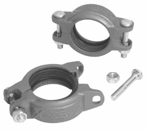
Fig. 6400
Rigid Coupling
The Figure 6400 Rigid Coupling is specially designed to provide a
rigid pipe connection to meet the specifc demands of copper tubing
installation size 2"-8". Fast and easy swing-over installation of the rugged
lightweight housing produces a secure rigid pipe joint. Available with
Grade “E” Copper EPDM fush gap style gasket. Gasket has service
temperature range of -40°F to +230°F. NSF 61 Certifed for cold +86°F
(+30°C) and hot +180°F (+82°C) potable water service.
Housing:
Ductile iron conforming to ASTM A-536, Grade 65-54-12
Coatings:
Rust inhibiting enamel paint — Color: Copper
For other coating requirements contact your Anvil Representative.
ANSI Bolts and Heavy Hex Nuts:
Heat treated carbon steel oval neck bolts conforming to the physical
properties of ASTM A 183 with a minimum tensile strength of 110,000
PSI. Bolts and nuts are provided zinc electroplated as standard.
Gaskets:
Grade “E” EPDM Flush Gap Gasket (Copper Color Code)
Service Temperature Range: -40°F to +230°F(-40°C to +110°C)
Recommended for water service, diluted acids, alkaline solutions, oil-
free air and many chemical services.
NOT FOR USE IN PETROLEUM APPLICATIONS.
NSF 61 Certifed for cold +86°F (+30°C) and hot +180°F (+82°C) potable
water service.
Figure 6400 Rigid Coupling
Nominal
Size
Copper
Tube
Diameter
Max Wk.
Pressure
Max
End
Load
Range of
Pipe End
Separation
Coupling Dimensions
Coupling Bolts
Approx.
Wt. Ea.
X
Y
Z
Qty.
Size
In.
In./mm
PSI/bar
Lbs./kN
In./mm
In./mm
In./mm
Lbs./Kg
2
2.125
54.0
300
20.7
1063
4.73
0 - 0.16
0 - 3.2
3.00
76
5.00
127
1.68
43
2
3
/
8
x 2
1
/
4
1.53
0.69
2
1
/
2
2.625
66.7
300
20.7
1623
7.22
0 - 0.16
0 - 3.2
3.50
89
5.50
140
1.68
43
2
3
/
8
x 2
1
/
4
1.78
0.81
3
3.125
79.4
300
20.7
2300
10.23
0 - 0.16
0 - 3.2
4.18
106
6.28
159
1.68
43
2
1
/
2
x 3
2.76
1.25
4
4.125
104.8
300
20.7
4007
17.82
0 - 0.17
0 - 4.2
5.20
132
7.50
191
1.70
43
2
1
/
2
x 3
3.27
1.48
5
5.125
130.2
300
20.7
6186
27.51
0 - 0.17
0 - 4.2
6.20
157
9.10
231
1.80
46
2
5
/
8
x 3
1
/
4
4.71
2.14
6
6.125
155.6
300
20.7
8835
39.30
0 - 0.17
0 - 4.2
7.20
183
10.20
259
1.80
46
2
5
/
8
x 3
1
/
4
5.24
2.38
8
8.125
206.4
300
20.7
15547
69.15
0 - 0.17
0 - 4.2
9.32
237
12.40
315
2.00
51
2
5
/
8
x 3
1
/
4
7.67
3.48
Pressure ratings and end loads are based on use with ASTM B88 Type K or L tubing. For pressure ratings on Type M and DWV, contact your Anvil Representative.
See Installation & Assembly directions on page 156.
material specifications
Y
Z
X
GL-2.10
Powered by FlippingBook Publisher