Page 123 - publication
SEO Version


Di-Lok®Nipples
Introduction
Couplings
Outlets
Fittings
Val
ves &
Accesso
ries
High
Pressure
Advanced Copper
Method (IPS)
DI-LOK
®
Nipples
Plain-End
Fittings
HDPE
Couplings
Sock-It
®
Fittings
Stainless
Steel Method
Roll
Groovers
Installation
& Assembly
Special
Coatings
Design
Services
Technical
Data
Master Format
3 Part Specs.
Pictorial
Index
CTS Copper
System
www.anvilintl.com
123
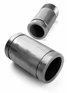
FIG. 7088, 7089 & 7090
Gruvlok DI-LOK
®
Nipple • Di-Electric Pipe Connection
The Gruvlok Fig. 7088, 7089 and 7090 DI-LOK Nipple inhibits
the formation of a galvanic cell between steel pipe and copper
tube at the transition from threaded or grooved-end steel pipe
to a Gruvlok Advanced Copper Method pipe system. Patented
Gruvlok Advanced Copper Method tube end preparation makes
it possible to connect copper tube to steel pipe using a standard
Gruvlok Figure 7400 Rigidlite Coupling or a Figure 7012 Gruvlok
Flange; costly special adapter couplings are not needed. Gruvlok
DI-LOK Nipples are easily installed between the copper tube and
steel pipe in groove to groove or groove to thread confgurations,
producing a dielectric connection.
The separation of copper from steel by the DI-LOK Nipple
virtually eliminates the galvanic cell created by the dissimilar
metals. The Gruvlok Figure 7400 Rigidlite Coupling and Figure
7012 Gruvlok Flange provide tines which produce an electrical
connection on the outside of the DI-LOK Nipple providing a
means for transmission of stray current outside of the fuid
media effectively eliminating acceleration of corrosion to the
wetted metals.
The Gruvlok DI-LOK Nipple is manufactured from ASTM A 513
steel tube which provides tighter dimensional controls to that
of steel pipe. The tube is zinc electroplated per ASTM B 633
which provides added corrosion resistance and produces an
attractive, easily identifed
appearance. Polypropylene molded
into the steel tube creates a liner
which meets the polypropylene
tube lining requirements of ASTM F
492. The polypropylene serves as a
dielectric insulator between the
copper tube and the steel pipe.
The grooved-ends are cut grooved to standard
Gruvlok groove dimensions, meeting the dimensional
requirements of AWWA C606. The NPT threaded end of the
DI-LOK Nipple is in conformance with ANSI B1.20.1.
The DI-LOK Nipple is designed for use at temperatures from -
40°F to 230°F (-40°C to 110°C) and pressures to 300 PSIG (20.7
bar) in a wide range of applications.
material specifications
HOUSING:
Steel Tube to ASTM A 513
LINER:
Polypropylene to ASTM D 4140
INSTALLATION & ASSEMBLY:
For installation and assembly of grooved-
end connections, see “Fig. 7400 Gruvlok Rigidlite Coupling” and “Fig.
7012 Gruvlok Flange”.
FIG. 7088 -
Groove by Thread
FIG. 7089 -
Groove by Groove
FIG. 7090 -
Thread by Thread
Figure 7088 available in Nominal Pipe Sizes 2" through 4" only.
Figure 7089 available in Nominal Pipe Sizes 2" through 6" only.
Figure 7090 available in Nominal Pipe Sizes
3
/
4
" through 2" only.
FIGURE 7088, 7089 & 7090 DI-LOK NIPPLES
Nom. IPS
Pipe Size O.D.
A
+/-.030
+/-.76
B
+/-.030
+/-.76
C Actual Tolerance
+0.000
D Actual
Tolerance
E
+/-.090
+/-2.29
Approx.
Wt. Ea.
NIPS/DN In./mm In./mm In./mm In./mm In./mm In./mm
In./mm
In./mm Lbs./Kg
3
/
4
1.050 n/a
n/a
7
/
8
n/a
1
1
/
16
+.005/-.000 3.000 0.2
19
26.7
22
26.7
+.13/-.00
76
0.1
1
1.315 n/a
n/a
1
1
/
8
n/a
1
5
/
16
+.005/-.000 4.000 0.4
25
33.7
28
33.7
+.13/-.00
102
0.2
1
1
/
4
1.660 n/a
n/a
1
1
/
2
n/a
1
11
/
16
+.006/-.000 4.000 0.6
32
42.4
37
42.4
+.15/-.00
102
0.3
1
1
/
2
1.900 n/a
n/a
1
11
/
16
n/a
2
+.006/-.000 4.000 0.8
40
48.3
43
48.3
+.15/-.00
102
0.4
2
2.375
5
/
8
5
/
16
2
1
/
4
-0.015 2
3
/
8
+.007/-.000 4.000 1.0
50
60.3
15.88
7.92
57
-0.37
60.3
+.18/-.00
102
0.5
2
1
/
2
2.875
5
/
8
5
/
16
2
3
/
4
-0.018 2
7
/
8
+.008/-.000 6.000 1.6
65
73.0
15.88
7.92
69
-0.45
73.0
+.20/-.00
152
0.7
3
3.500
5
/
8
5
/
16
3
3
/
8
-0.018 3
1
/
2
+.010/-.000 6.000 2.0
80
88.9
15.88
7.92
85
-0.45
88.9
+.25/-.00
152
0.9
4
4.500
5
/
8
3
/
8
4
5
/
16
-0.020 4
1
/
2
+013/-.000 6.000 4.5
100
114.3
15.88
9.53
110
-0.50
114.3
+.33/-.00
152
2.0
5
5.563
5
/
8
3
/
8
5
3
/
8
-0.022 5
9
/
16
±.010
6.000 7.3
125
141.3
15.88
9.53
137
-0.55
141.3
±.25
152
3.3
6
6.625
5
/
8
3
/
8
6
1
/
2
-0.022 6
5
/
8
±.015
6.000 9.5
150
168.3
15.88
9.53
164
-0.55
168.3
±.38
152
4.3`
STEEL TUBE
E
B
A
PO LYPROPYLENE
STEEL TUBE
E
B
A
PO LYPROPYLENE
E
GL-2.10
Powered by FlippingBook Publisher