Page 150 - publication
SEO Version


gruvlok installation and assembly
www.anvilintl.com
150
COUPLING INSTALLATION & ASSEMBLY
The instructions are based on pipe grooved in accordance with
Gruvlok® grooving specifcations. Check pipe ends for proper
groove dimensions and to assure that the pipe ends are free of
indentations and projections which would prevent proper sealing.
ALWAYS USE A GRUVLOK®LUBRICANT FOR PROPER COUPLING
ASSEMBLY. Thorough lubrication of the external surface of the
gasket is essential to prevent pinching and possible damage to
the gasket. For temperatures above 150° F (65.6° C) use Gruvlok
Xtreme
TM
Lubricant and lubricate all gasket surfaces, internal
and external. See Gruvlok Lubricants in the Technical Data
section of the Gruvlok catalog for additional important
information.
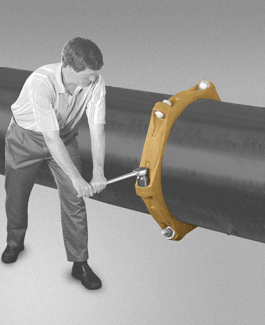
SPECIFIED BOLT TORQUE
Specifed bolt torque is for the oval neck track bolts used on
Gruvlok® couplings and fanges. The nuts must be tightened
alternately and evenly until fully tightened. Caution: Use of an
impact wrench is not recommended because the torque
output can vary signifcantly due to many variables including
air pressure supply, battery strength and operational variations.
CAUTION:
Proper torquing of coupling bolts is required to obtain specifed
performance. Over torquing the bolts may result in damage to the bolt and/or
casting which could result in pipe joint separation. Under torquing the bolts may
result in lower pressure retention capabilities, lower bend load capabilities, joint
leakage and pipe joint separation. Pipe joint separation may result in signifcant
property damage and serious injury.
ANSI SPECIFIED
BOLT TORQUE
Bolt
Size
Wrench
Size
Specifed
Bolt Torque *
In.
In.
Ft.-Lbs
3
/
8
11
/
16
30-45
1
/
2
7
/
8
80-100
5
/
8
1
1
/
16
100-130
3
/
4
1
1
/
4
130-180
7
/
8
1
7
/
16
180-220
1
1
5
/
8
200-250
1
1
/
8
1
13
/
16
225-275
1
1
/
4
2
250-300
METRIC SPECIFIED
BOLT TORQUE
Bolt
Size
Wrench
Size
Specifed
Bolt Torque *
mm mm
N-m
M10
16
40-60
M12
22
110-150
M16
24
135-175
M20
30
175-245
M22
34
245-300
M24
36
270-340
NOTE:
Specifed torques are to be used unless otherwise noted on Product Installation Instructions.
* Non-lubricated bolt torques.
* Non-lubricated bolt torques.
Installation & Assembly
TABLE OF CONTENTS
FIG. 7001
Standard Coupling................................................ 151
FIG. 7011
Standard Coupling................................................ 152
FIG. 7401
Rigidlok®Coupling................................................ 153
FIG. 7000
Lightweight Flexible Coupling..................... 154
FIG. 7400
Rigidlite®Coupling.............................................. 155
FIG. 6400
Rigid Coupling...................................................... 156
FIG. 7003
Hingelok
TM
Coupling.......................................... 157
FIG. 7010
Reducing Coupling............................................. 158
FIG. 7012
Gruvlok Flange (2" - 12")............................. 159-160
FIG. 7012
Gruvlok Flange (14" - 24")....................................161
FIG. 7042
Outlet Coupling .................................................. 162
FIG. 7045
&
FIG. 7046
Clamp-T® Branch Outlets....... 163
FIG. 7005
Roughneck®Coupling........................................164
FIG. 7305
HDPE Coupling...................................................... 165
FIG. 7307
HDPE Transition Coupling................................166
FIG. 7312
HDPE Flange Adapter.......................................... 167
Gruvlok Sock-It® Fitting
........................................................168
Model FTV
Tri-Service Valve.......................................169-172
Series GBV-S & GBV-T
Circuit Balancing Valves .. 173-175
FIG. AF21-GG, -GF & -FF
AnvilFlex
TM
............................... 176
GL-2.10
Powered by FlippingBook Publisher