Page 161 - publication
SEO Version


gruvlok installation and assembly
Introduction
Couplings
Outlets
Fittings
Val
ves &
Accesso
ries
High
Pressure
Advanced Copper
Method (IPS)
DI-LOK
®
Nipples
Plain-End
Fittings
HDPE
Couplings
Sock-It
®
Fittings
Stainless
Steel Method
Roll
Groovers
Installation
& Assembly
Special
Coatings
Design
Services
Technical
Data
Master Format
3 Part Specs.
Pictorial
Index
CTS Copper
System
www.anvilintl.com
161
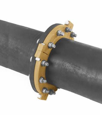
FIG. 7012
Gruvlok Flange (14"–24")
Gruvlok
®
Flanges of 14" size and larger are cast in four segments to ease handling during assembly.
1
Place each Gruvlok Flange segment around
the grooved pipe with the key section ftting
into the groove and the fange gasket cavity
facing the pipe end. Loosely assemble the
segments using the four segment-bolts-and
nuts. Alternately and equally tighten the latch
bolts and nuts to the specifed latch bolt torque.
Bring the four fange segments into full, frm
metal-to-metal contact.
NOTE:
An alternative method of assembly is
to loosely preassemble two segments into two
equal halves of the fange leaving a small gap
(approximately
1
/
8
") between the two segments
of each fange-half. Place the fange halves
around the pipe and complete the assembly as
described in Step 1, above.
2
Check the gasket grade to verify that it is
properly suited for the intended service.
Lubricate the entire surface of the gasket and
the fange cavity using the appropriate Gruvlok
Lubricant. Place the Gruvlok Flange Gasket
around the pipe end by pressing the gasket
into the cavity between the pipe O.D. and
fange recess. Move around the gasket in both
directions until the gasket is fully seated in the
fange gasket cavity.
3
The correct position and relationship of
the components of the Gruvlok Flange
assembly is shown in the Figure above. The
wide gasket lip must seal on the pipe surface
diameter and the narrow gasket lip must face
the mating fange. Be careful that foreign
particles do not adhere to lubricated surfaces.
NOTE:
Design of the Gruvlok Flange provides
sealing only with the special Gruvlok Flange
gasket. Only Gruvlok Flange gaskets may be
used with Fig. 7012 fanges.
4
Align the Gruvlok
Flange bolt holes
with mating fange bolt
holes. Insert a fange
bolt or stud with
material properties of
SAE J429 Grade 5 or
higher through the bolt
holes and thread a nut
on hand tight. Insert the
next bolt or stub
opposite the frst and
again thread the nut on hand tight. Continue this procedure until all bolt
holes have been ftted. Insertion of the fange bolts prior to contact of the
fanges will help in the alignment of the fanges. Pull the two fanges into
contact using care to assure that the gasket remains fully seated within the
gasket cavity during assembly.
NOTE:
Take care to assure that the gasket lip is not bent backwards and
pinched between the two fanges.
5
Tighten the nuts
evenly to the
specifed mating face
bolt torque so that the
fange faces remain
parallel and make frm
even contact around
the entire fange.
CAUTION:
Proper torquing of fange bolts is required to obtain specifed performance.
Over torquing the bolts may result in damage to the bolt and/or casting which could
result in pipe joint separation. Under torquing the bolts may result in lower pressure
retention capabilities, lower bend load capabilities, joint leakage and pipe joint separation.
Pipe joint separation may result in signifcant property damage and serious injury.
CAUTION:
Use of an impact wrench is not recommended because the torque output can
vary signifcantly due to many variables including air pressure supply, battery strength and
operational variations.
CAUTION:
GASKET
MUST BE
FULLY
SEATED
AGAINST
THESE
THREE
SURFACES
14" – 24" FIG. 7012
GRUVLOK FLANGE
GASKET
PROPER POSITION OF
GASKET SEALING LIPS
PIPE SURFACE DIAMETER
GL-2.10
Powered by FlippingBook Publisher