Page 176 - publication
SEO Version


gruvlok installation and assembly
www.anvilintl.com
176
Installation
1
Avoid torque. Do not twist the hose
assembly during installation when aligning
the bolt holes in a fange or in making up pipe
threads. The utilization of lap joint fanges or
pipe unions will minimize this condition.
2
To install a thread end braided metal hose
assembly unions must be used. Do not
place wrenches on the braided portion or the
collar of the braided metal hose assembly.
Use care not to torque the braided metal
hose assembly while tightening the union. It is
recommended that two wrenches be used in
making the union connection; one to prevent
the hose from twisting and the other to tighten
the coupling.
3
Install the braided metal hose assembly
with neutral face-to-face dimension as
shown on the submittal drawing. Do not install
a braided metal hose assembly compressed
(bagged braid). The corrugated inner hose
contains the fuid, the braid is designed to take
the stress of system pressurization and contain
the core.
4
If the braided metal hose assembly must
be installed with an initial offset then the
maximum allowable movement is reduced by
the amount of the initial defection.
5
Avoid over bending. The repetitive bending
of a hose assembly to a radius smaller than
the radius specifed will result in early hose
failure. Always provide suffcient length to
prevent over bending and to eliminate strain
on the hose assembly. Utilize sound geometric
confgurations that avoid sharp bends, especially
near the end fttings of the assembly.
6
Verify that the movements of the system
are within the design parameters of the
braided metal hose assembly being installed.
7
Prevent out-of-plane fexing in an
installation. Always install the hose
assembly so that the fexing takes place in only
one plane—this being the plane in which the
bending occurs.
8
The maximum system test pressure must
not exceed 150% of the maximum rated
working pressure as shown.
9
Check system pressure and temperature and
do not exceed recommended performance
limits. Operation beyond design limits will result
in premature failure.
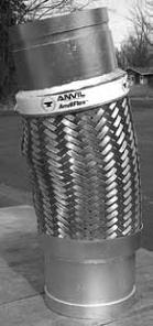
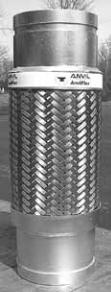
ANVILFLEX
™
FIG. AF21-GG, -GF & -FF
Flex Connectors
10
The corrugated metal hose alloy must
be chemically compatible with the
media in the piping system. If in doubt as to
suitability, refer to a Chemical Resistance Data
table or contact your Gruvlok rep. for guidance.
11
The fanges on a concentric increasing
braided metal hose assembly have
the bolt holes straddling the hose centerline.
The mating fanges should also straddle the
centerline to avoid torque on the braided metal
hose assembly.
12
When installing weld end, or sweat end,
braided metal hose assemblies, or when
welding in the area of a braided metal hose
assembly, extreme care is necessary in ensure no
weld spatter comes in contact with the braided
hose sections.
13
A piping system, which utilizes braided
metal hose to absorb movement, must
be properly anchored and/or guided. Always
support the piping to prevent excessive weight
from compressing the hose and relaxing the
braid tension.
14
Use care when handling the braided
metal hose assembly during
transportation, storage, and installation. The
braided hose sections must not be allowed to
bend, defect, sag, or otherwise extend beyond
their rated capabilities.
15
The shipping sticks, on fanged
units, are to keep the braided metal
hose assembly in its neutral end-to-end
dimension during shipping and installation.
After installation, the shipping sticks should be
removed.
Maintenance
1
The braided metal hose assembly should
be inspected during routine maintenance
to ensure there are no signs of external damage.
Inspect for frayed or broken braid wires. Also
inspect to ensure there is no damage to the
hose. In the event that such damage is found,
the braided metal hose assembly should be
replaced.
2
During system shutdown braided metal
hose assembly should be examined to verify
no thermal axial motion has occurred causing
compression of the assembly.
Groove x Groove
Proper Installation
Groove x Groove
Improper Installation
Parallel
Groove x Groove
Improper Installation
Compressed
GL-2.10
Powered by FlippingBook Publisher