Page 202 - publication
SEO Version


technical data
www.anvilintl.com
202
PIPE TOLERANCES
Size
Schedule 10 & 40 Min.
O.D.
XL Min.
O.D.
Nom O.D. Max. O.D.
DN/mm In./mm
In./mm In./mm In./mm
1 1.315
1.325 1.295 1.285
25
33.4
33.6
32.9 32.6
1
1
/
4
1.660
1.670 1.642 1.630
32
42.2
42.4
41.7 41.4
1
1
/
2
1.900
1.910 1.882 1.875
40
48.3
48.5
47.8 47.6
2 2.375
2.385 2.357 2.352
50
60.3
60.6
59.9 59.7
2
1
/
2
2.875
2.904 2.846 2.837
65
73.0
73.8
72.3 72.1
CLAMP-T INSTALLATION
Branch
Size
Hole Dimensions
Surface
Prep. “A”
Hole Saw Size Max. Perm. Diameter
DN/mm
In./mm
In./mm
In./mm
1
/
2
,
3
/
4
, 1
1
1
/
2
1
5
/
8
3
1
/
2
15, 20, 25
38.1
41.3
88.9
1
1
/
4
, 1
1
/
2
2
2
1
/
8
4
32, 40
50.8
54.0
101.6
2
2
1
/
2
2
5
/
8
4
1
/
2
50
63.5
66.7
114.3
2
1
/
2
2
3
/
4
2
7
/
8
4
3
/
4
65
69.9
73.0
120.7
3
3
1
/
2
3
5
/
8
5
1
/
2
80
88.9
92.1
139.7
4
4
1
/
2
4
5
/
8
6
1
/
2
100
114.3
117.5
165.1
PIPE-PREPARATION:
BRANCH OUTLET PIPE: CLAMP-T
®
Clamp-T installations require the cutting
of a hole through the pipe wall. The hole
must be properly sized and located on the
centerline of the pipe to assure reliable
performance of the Clamp-T gaskets.
After the hole has been cut into the pipe
wall, any burrs and sharp or rough edges
must be removed from the hole. The outside pipe surfaces within
5
/
8
" of the hole
must be clean and smooth. Any scale, projections or indentation which might
effect the gasket sealing on the pipe must be removed. The surface around the
entire circumference of the pipe within the “A” dimension in the charts must be
free from dirt, scale, or projections which might effect the proper assembly of
the Clamp-T.
SOCK-IT
®
For Sock-It Fittings, the pipe ends must be square cut as measured from a
true square line.
The maximum allowable tolerance is 0.030" (0.76mm) for all sizes. Any
sharp edges, burrs, etc. left on the pipe from cutting must be removed. If
these are not removed, they may damage the gasket as the pipe is inserted
into the Sock-It Fitting.
After cutting, pipe ends must be completely cleaned a minimum of 1"
(25.4mm) back from the pipe end to remove all pipe coating, weld beads,
rust, sharp projections, etc., which might effect gasket sealing integrity.
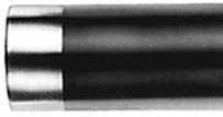
ACCEPTABLE PIPE END
CONFIGURATION
NOTE:
When Allied XL pipe
is used it is necessary only
to remove sharp edges and
burrs at the end of the pipe.
No additional cleaning is
required.
ROUGHNECK
®
A
5
/
8
"
Square cut pipe with O.D.
burr & sharp edge removed
is preferred confguration.
Beveled pipe. Bevel not
to exceed
1
/
16
".
Soft pipe when roll cut may
be swaged inward. Swaged
portion not to exceed
3
/
16
"
Remove Burr
& Sharp Edge
30 or
45
1
/
32
" to
1
/
16
"
3
/
16
" Max.
Plain-End pipe for use with Fig. 7005 Roughneck Couplings must be free
of any notches, bumps, weld bead, score marks, etc. for at least 1
1
/
2
" (38
mm) back from the pipe end to provide a smooth sealing surface for the
gasket. Pipe ends (plain or beveled end) must be square cut as measured
from a true square line with the maximum allowable tolerance as follows:
0.030" (0.7 mm) for 2" through 3"; 0.045 (1.1 mm) for 4" through 6"; and 0.060"
(1.5 mm) for 8" sizes. The nominal outside diameter of pipe should not
vary more than
±
1% for sizes up to 2
1
/
2
", +1%-
1
/
32
” for sizes 3"-5"; +
1
/
16
”-
1
/
32
" for
sizes 6" and larger. Pipe ends must be marked a distance of 1" from the pipe
end for Sizes 2"-4" and 1
1
/
4
" from the pipe end for Sizes 5"-8" as a guide for
centering of the gasket on the pipe ends.
UNACCEPTABLE
The sharp O.D. edge left by different methods of cutting pipe
must be removed
. If this
sharp edge is not removed, it may damage the gasket as the pipe is inserted into the
Sock-It Fitting.
Excessive chamfer on I.D.
will tend to cut gasket
during assembly.
Abrasive wheels & saws
leave edge burrs especially
pronounced on one side.
Dull wheel cutter produces a
raised ridge at the pipe O.D.
giving an oversize diameter.
GL-2.10
Powered by FlippingBook Publisher