Page 79 - publication
SEO Version


Valves & Accessories
Introduction
Couplings
Outlets
Fittings
Val
ves &
Accesso
ries
High
Pressure
Advanced Copper
Method (IPS)
DI-LOK
®
Nipples
Plain-End
Fittings
HDPE
Couplings
Sock-It
®
Fittings
Stainless
Steel Method
Roll
Groovers
Installation
& Assembly
Special
Coatings
Design
Services
Technical
Data
Master Format
3 Part Specs.
Pictorial
Index
CTS Copper
System
www.anvilintl.com
79
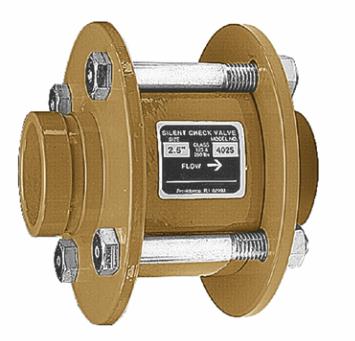
FIGURE 400G GROOVED-END SILENT CHECK VALVE
Valve
Size
O.D.
Model
A
B
Cv
Flow *
Approx.
Wt. Each
In./mm
In./mm
Number
In./mm
In./mm
Lbs./Kg
2
2.375
402G
6
6
66
12
50
60.3
152
152
1,676
5.4
2
1
/
2
2.875
4025G
6
1
/
4
7
88
15
65
73.0
159
178
2,235
6.8
3
3.500
403G
6
7
/
16
7
1
/
2
130
20
80
88.9
164
191
3,302
9.1
4
4.500
404G
8
1
/
8
9
228
36
100
114.3
206
229
5,791
16.3
5
5.563
405G
11
1
/
4
10
350
50
125
141.3
286
254
8,890
22.7
6
6.625
406G
12
1
/
4
11
520
68
150
168.3
311
279
13,208
30.8
8
8.625
408G
13
3
/
4
13
1
/
2
900
140
200
219.1
349
343
22,860
63.5
10
10.750
410G
16
16
1,450
198
250
273.1
406
406
36,830
89.8
MAX. NON-SHOCK WORKING PSI
125# ANSI B16.1 FLANGE RATING
Size
Temperature
2" - 10"
150°F
200°F
65°C
90°C
200 PSI
190 PSI
13.8 bar
13.1 bar
MATERIAL SPECIFICATIONS
FIG. 400G
Grooved-End Silent Check Valve
Available in Sizes 2" thru 10"
The 400G is a center guided, spring loaded,
silent check valve. Designed and engineered
for silent operation with low head loss, the
valve disc will close prior to the reversal of
fow, thereby preventing or minimizing water
hammer and damaging shock.
• The 400G can be used in any HVAC,
industrial or commercial grooved piping
systems.
• The valve is designed for liquid service
with any pipe orientation, fow up or
down.
• Bronze metal seats are standard, with
Stainless Steel or resilient seats available
as an option.
• Flow coeffcients for this valve are some
of the lowest in the industry and are
listed for each size on the drawing.
NOTE:
Valve is designed for liquid service only. Install 3 to 4 pipe
diameters downstream from pump discharge or elbows to
avoid fow turbulence.
STANDARD MATERIALS:
Cast Iron body ASTM A 48, Class 35
Bronze Disc and Seat ASTM B 584 Alloy 838
Ductile Iron Grooved-Ends ASTM A 395
OPTIONAL TRIM MATERIALS:
Bronze with Nitrile seats
Stainless Steel seats
Stainless with Nitrile seats
1. BODY:
Cast Iron ASTM A 48, Class 35
2. SEAT:
Bronze ASTM B 584, Copper Alloy 838
3. PLUG:
Bronze ASTM B 584, Copper Alloy 838
4. SPRING:
Stainless Steel T304, ASTM A 313
5. BUSHING:
Bronze ASTM B 584, Copper Alloy 836
6. SCREWS:
Stainless Steel T304, ASTM A 276
7. GROOVED-END:
Ductile Iron ASTM A 395
8. GASKET:
Non Asbestos
For gasket grade recommendations see the
Technical Data section
9. BOLTS:
Carbon Steel
Other materials and resilient seats are available...
contact your Sales representative.
A
B
9
1
2
3
4
5
6
7
8
8
Cv FLOW
* Flow coeffcient is the number of U.S. gallons/minute of 60° F (16° C) water that will fow through a valve with 1 psi
(0.069 bar) of pressure drop across the valve.
GL-2.10
Powered by FlippingBook Publisher