Page 25 - GarlockFluidSealing2010
SEO Version


A-23
Installation Instructions
1. Remove all of the old packing from the stuffng box.
Clean box and stem thoroughly and examine stem
for wear and scoring. Replace stem if wear is exces-
sive. Recommended surface fnishes are 32 (micro
inches) AARH on the stem, and 125 (micro inches)
AARH maximum on the box bore.
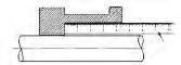
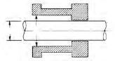
2. Measure and record stem diameter, stuffng box
bore and box depth. To determine the correct pack-
ing size, measure the diameter of the stem (inside
the stuffng box area if possible), and the diameter of
the stuffng box bore. Subtract the I.D. measurement
from the O.D. measurement, and divide the differ-
ence by two. This is the required cross-sectional
size.
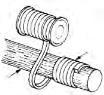
3. Always cut the packing into individual rings. Never
wind the packing into a coil in the stuffng box. Rings
should be cut with a butt joint. Cut rings by using a
spare stem, a mandrel with the same diameter as
the stem or a packing cutter. The illustration shows
how to use a mandrel to cut packing.
Hold the packing tightly on the mandrel, but do not
stretch excessively. Cut the ring and insert it into the
stuffng box, making certain that it fts the packing
space properly. Each additional ring can be cut in
the same manner.
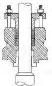
4. Install one ring at a time. Make sure it is clean, and
has not picked up any dirt in handling. Seat each
ring frmly, making sure it is fully seated before the
next ring is installed. Joints of successive rings
should be staggered and kept at least 90° apart.
When enough rings have been individually seated
so that the nose of the gland follower will reach
them, individual tamping of the rings should be
supplemented by the gland follower. Bring down the
gland follower and apply load with the gland bolts.
5. After the last ring is installed, bring down the gland
follower and apply 25% to 35% compression to the
entire packing set. If possible, record the gland nut
torque values and actuate the valve through fve (5)
complete cycles (ending with the stem in the down
position). Retighten the gland bolt nuts to the pre-vi-
ously recorded torque value after each full actuation.
Step 1
Step 2
Ruler
I.D.
O.D.
Do Not
Stretch
Packing
Mandrel
Step 3
Steps 4 and 5
Butt Cut
Joints
Valve Stem Packing
Powered by FlippingBook Publisher