Page 43 - GarlockFluidSealing2010
SEO Version


B-11
PTFE Control Units and Flanges
All PTFE joints and couplings are furnished with
ductile iron fanges and control units ready for immedi-
ate installation on the job site. Flanges in other alloys
are available by special order.
Flanges
are protected to resist atmosphere corrosion
and are tapped to 150 Ibs. ANSI Standard drilling.
Control units
are assembled with fanges to prevent
joints from excessive axial elongation. They are
designed to accept the static pressure thrust in the
piping system.
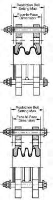
Tie rods
are set at the factory at the maximum face-
to-face working limits, with lock nuts as insurance
against overextension of the expansion joint. The
tie rods are covered with polyethylene to elimi-
nate metal-to-metal contact between the rods and
fanges—the most frequent cause of noise trans-
mission and electrolysis.
Movement
Flange Dimensions and Drilling
Style 214 PTFE Flexible Couplings
Pipe Size (Inches)
1
1-1/2
2
2-1/2
3
4
5
6
8
Nominal Installed
Face to-Face
1-3/8
1-3/8
1-9/16
2-1/4
2-1/4
2-5/8
3-1/4
2-3/4
4
Max. Restriction Bolt
Setting
1-1/4
1-5/16 1-15/32 2-7/32
2-1/4
2-23/32 3-5/16
2-3/4
4
Max. Axial Movement
+ or -
1/4
1/4
1/4
5/16
3/8
1/2
1/2
1/2
1/2
Max. Transverse
Defection, + or -*
1/8
1/8
1/8
1/8
3/16
1/4
1/4
1/4
1/4
Maximum angular movement aproximately 7°.
* Based on unit being in normal installed position with no axial movement or angular defection.
Style 215 PTFE Flexible Couplings
Pipe Size (Inches)
1
1-1/2
2
2-1/2
3
4
5
6
8
Nominal Installed
Face to-Face
1-3/4
2
2-3/4
3-3/16
3-5/8
3-5/8
4
4
6
Max. Restriction Bolt
Setting
1-7/8
2-5/32
3-5/32
3-9/16
4-1/4
4-1/4
4-9/16
4-5/8
6-5/8
Max. Axial Movement
+ or -
1/2
1/2
3/4
3/4
1
1
1
1-1/8
1-1/8
Max. Transverse
Defection, + or -*
1/4
1/4
3/8
3/8
1/2
1/2
1/2
9/16
9/16
Maximum angular movement aproximately 14°.
* Based on unit being in normal installed position with no axial movement or angular defection.
Pipe Size (Inches)
1
1-1/2
2
2-1/2
3
4
5
6
8
Flange
Dimension
5-11/16 6-7/16
7-7/8
9-1/8
10
11-1/8
12-7/8
13-7/8
15-1/2
Thickness
3/8
3/8
1/2
5/6
5/8
11/16
11/16
11/16
11/16
ANSI Std. Drilling
Bolt Circle Dia.
3-1/8
3-7/8
4-3/4
5-1/2
6
7-1/2
8-1/2
9-1/2
11-3/4
No. Bolt Holes
4
4
4
4
4
8
8
8
8
Bolt Hole Thread
1/2-13
1/2-13
5/8-11
5/8-11
5/8-11
5/8-11
3/4-10
3/4-10
3/4-10
* Special order only
Powered by FlippingBook Publisher