Page 120 - publication
SEO Version


CTS Copper System
www.anvilintl.com
120
Concentric
Reducers
Dimensions/Weights – Reducers
Nominal
Size
Fig. 6072
Groove x Groove
Fig. 6075
Groove x Cup
E to E
Wt. Ea
E to E Cup Length Wt Ea.
In.
In./mm
Lbs./kg
In./mm
In./mm
Lbs./kg
2 x 1
–
–
–
–
2.70
68.6
0.91
23.1
0.32
0.15
2 x 1
1
/
4
–
–
–
–
3.00
76.2
0.97
24.6
0.36
0.16
2 x 1
1
/
2
–
–
–
–
2.94
74.7
1.09
27.7
0.38
0.17
2
1
/
2
x 1
–
–
–
–
3.25
82.6
0.91
23.1
0.53
0.24
2
1
/
2
x 1
1
/
4
–
–
–
–
3.52
89.4
0.97
24.6
0.59
0.27
2
1
/
2
x 1
1
/
2
–
–
–
–
3.45
87.6
1.09
27.7
0.59
0.27
2
1
/
2
x 2
3.29
83.6
0.58
0.26
3.30
83.8
1.34
34.0
0.58
0.26
3 x 1
1
/
2
–
–
–
–
3.68
93.5
1.09
27.7
0.84
0.38
3 x 2
2.50
63.5
0.58
0.26
4.10
104.1
1.34
34.0
0.97
0.44
3 x 2
1
/
2
2.50
63.5
0.62
0.28
–
–
–
–
–
–
4 x 2
4.75
120.7
1.71
0.78
4.75
120.7
1.34
34.0
1.76
0.80
4 x 2
1
/
2
3.00
76.2
1.12
0.51
–
–
–
–
–
–
4 x 3
3.00
76.2
1.22
0.55
–
–
–
–
–
–
5 x 3
3.88
98.6
2.11
0.96
–
–
–
–
–
–
5 x 4
3.38
85.9
1.97
0.89
–
–
–
–
–
–
6 x 3
4.38
111.3
2.96
1.34
–
–
–
–
–
–
6 x 4
3.88
98.6
2.87
1.30
–
–
–
–
–
–
6 x 5
3.38
85.9
2.78
1.26
–
–
–
–
–
–
8 x 6
5.00
127.0
6.60
2.99
–
–
–
–
–
–
Fig. 6072
Fig. 6075
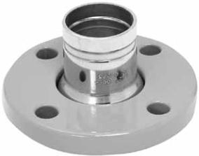
Fig. 6084
Flange Adapter
The Gruvlok®Fig. 6084 Flange Adapter allows for direct connection
of Class 125 or Class 150 fanged components to the CTS Copper
System. The CTS Copper Flange Adapter (Sizes 2" thru 6") conform to
ANSI class 125/150 bolt patterns and is rated at 300 PSIG (20.7 bar).
The fange is powder coated with Nylon-11.
Figure 6084 Flange Adapter
Nominal
Size
Copper Tube
Diameter
E to E
Approx.
Wt. Ea.
In.
In./mm
In./mm
Lbs./kg
2
2.125
54.0
3.0
76.2
0.85
0.39
2½
2.625
66.7
3.5
88.9
1.34
0.61
3
3.125
79.4
3.5
88.9
1.73
0.78
4
4.125
104.8
3.5
88.9
2.43
1.10
5
5.125
130.2
3.5
88.9
3.27
1.48
6
6.125
155.6
4.0
101.6
4.78
2.17
E to E
E to E
Cup
E to E
GL-2.10
Powered by FlippingBook Publisher