Page 159 - publication
SEO Version


gruvlok installation and assembly
Introduction
Couplings
Outlets
Fittings
Val
ves &
Accesso
ries
High
Pressure
Advanced Copper
Method (IPS)
DI-LOK
®
Nipples
Plain-End
Fittings
HDPE
Couplings
Sock-It
®
Fittings
Stainless
Steel Method
Roll
Groovers
Installation
& Assembly
Special
Coatings
Design
Services
Technical
Data
Master Format
3 Part Specs.
Pictorial
Index
CTS Copper
System
www.anvilintl.com
159
FIG. 7012
Gruvlok Flange (2"–12")
APPLICATIONS WHICH REQUIRE A GRUVLOK®FLANGE ADAPTER INSERT:
1. When mating to a wafer valve (lug valve), if the valve is rubber faced in
the area designated by the sealing surface dimensions (A Max. to B Min.),
place the Gruvlok Flange Adapter Insert between the valve and the
Gruvlok Flange.
2. When mating to a rubber-faced metal fange, the Gruvlok Flange
Adapter Insert is placed between the Gruvlok Flange and the rubber-
faced fange.
3. When mating to a serrated fange surface, a standard full-faced fange
gasket is installed against the serrated fange face, and the Gruvlok
Flange Adapter Insert is placed between the Gruvlok Flange and the
standard fange gasket.
4. When mating to valves or other component equipment where the
fange face has an insert, use procedure described in note 3.
Check pipe end for proper grooved dimensions and to assure that the
pipe end is free of indentations and projections that would prevent
proper sealing of the Gruvlok fange gasket.
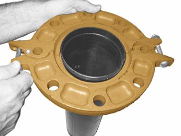
1
On the side without the hinge pin, loosen
the latch bolt nut to the end of the bolt
thread. (It is not necessary to remove the nut
from the latch bolt.) Swing the latch bolt out
of the slot. Open the Gruvlok Flange and place
around the grooved pipe end with the key
section ftting into the groove. The fange gasket
cavity must face the pipe end.
2
Place the latch bolt back into the slotted
hole. Tighten the nut until there is a
1
/
16
" gap
between the fange halves at location “A”. (See
Figure below)
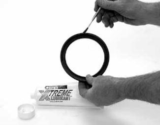
3
Check the gasket to assure that it is
properly suited for the intended service.
Lubricate the entire exterior surface of the
gasket, including the sealing lips, using the
proper Gruvlok lubricant.
NOTE:
VdS - Roll Grooving Approval
Specifcations, see the Technical Data/
Installation Instructions section on Anvil’s
web site - www.anvilintl.com
The Gruvlok Flange gasket must be inserted so that the sealing lips face
toward the pipe end and the mating fange. The lip of the gasket, sealing
on the pipe, should not extend beyond the pipe end. The pipe should
extend out beyond the end of the sealing lip by approximately
1
/
8
" on
the 2"-6" sizes and
3
/
16
" on the 8"-12" sizes.
"A"
Latch Bolt
Gasket
Note: This side must
face the mating flange
GL-2.10
Powered by FlippingBook Publisher