Page 158 - publication
SEO Version


gruvlok installation and assembly
www.anvilintl.com
158
FIG. 7010
Reducing Coupling
1
Check & lubricate gasket—
check gasket to be sure it is compatible for
the intended service. Apply a thin coating of
Gruvlok lubricant to outside and sealing lips of
the gasket. Be careful that foreign particles do
not adhere to lubricated surfaces.
2
Gasket Installation—
Place
the smaller opening of the gasket over the
smaller pipe. Angle the gasket over the pipe
end and pull the gasket lip open around the
circumference of the pipe. The center leg of the
gasket should make fush contact with the pipe
end and will prevent telescoping of the smaller
pipe inside the larger.
3
Alignment—
Align the adjoining pipe
center lines, and insert the larger pipe end
into the gasket. Angle the pipe end slightly to
the face of the gasket and tilt the pipe into the
gasket to ease assembly.
CAUTION:
Use of an impact wrench is not recommended because the torque output can
vary signifcantly due to many variables including air pressure supply, battery strength and
operational variations.
CAUTION:
Proper torquing of coupling bolts is required to obtain specifed performance.
Over torquing the bolts may result in damage to the bolt and/or casting which could
result in pipe joint separation. Under torquing the bolts may result in lower pressure
retention capabilities, lower bend load capabilities, joint leakage and pipe joint separation.
Pipe joint separation may result in signifcant property damage and serious injury.
NOTE:
VdS - Roll Grooving Approval Specifcations, see the Technical Data/Installation Instructions section on Anvil’s web site - www.anvilintl.com
4
Housings—
Place the
coupling housing halves over
the gasket making sure the housing
keys engage the grooves. Insert
bolts and turn nuts fnger tight.
5
Tighten Nuts—
Tighten the nuts alternately
and equally to the specifed bolt
torque. The housing bolt pads must
make metal-to-metal contact.
CAUTION:
Uneven tightening may
cause the gasket to pinch.
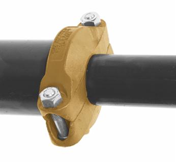
6
Assembly Complete—
Visually inspect the pipe joint
to assure the coupling keys are
fully engaged in the pipe grooves
and the bolt pads are in frm even
metal-to-metal contact on both
sides of the coupling.
NOTE:
Fig. A illustrates the correct
position of the Fig. 7010 Reducing
Coupling gasket and housing
properly assembled onto adjacent
pipe ends.
CAUTION:
In vertical installations
the pipes must be supported
to prevent telescoping during
installation.
Gasket
Center Rib
Proper
Position of
The Gasket
Sealing Lips
Gasket
Reducing
Coupling
Housing
Fig. A
GL-2.10
Powered by FlippingBook Publisher