Page 163 - publication
SEO Version


gruvlok installation and assembly
Introduction
Couplings
Outlets
Fittings
Val
ves &
Accesso
ries
High
Pressure
Advanced Copper
Method (IPS)
DI-LOK
®
Nipples
Plain-End
Fittings
HDPE
Couplings
Sock-It
®
Fittings
Stainless
Steel Method
Roll
Groovers
Installation
& Assembly
Special
Coatings
Design
Services
Technical
Data
Master Format
3 Part Specs.
Pictorial
Index
CTS Copper
System
www.anvilintl.com
163
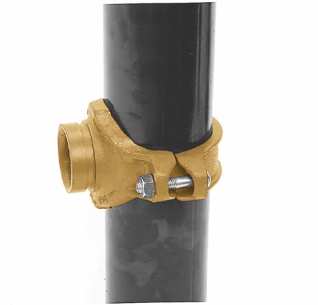
FIG. 7045 & FIG. 7046
Clamp-T
®
Branch Outlets
ALWAYS USE A GRUVLOK LUBRICANT FOR PROPER COUPLING ASSEMBLY.
Thorough lubrication of the gasket is essential to assist the gasket into the proper sealing position.
1
Pipe preparation—
Cut the
appropriate size hole in the pipe and
remove any burrs. Be sure to remove the slug
from inside the pipe. Clean the gasket sealing
surface within
5
/
8
" of the hole and visually
inspect the sealing surface for defects that may
prevent proper sealing of the gasket.
2
Check & lubricate gasket—
Check the gasket to be sure it is compatible
for the intended service. Apply a thin layer of
Gruvlok lubricant to the back surface of the
gasket. Be careful that foreign particles do not
adhere to the lubricated surfaces. Insert the
gasket back into the outlet housing making
sure the tabs in the gasket line up with the tab
recesses in the housing.
3
Gasket Installation—
Lubricate
the exposed surface of the gasket. Align the
outlet housing over the pipe hole making sure
that the locating collar is in the pipe hole.
4
Alignment—
Align the strap around
the pipe, insert the bolts and tighten the
nuts fnger tight. Some sizes use a U-bolt design.
5
Tighten nuts—
Alternately and
evenly tighten the nuts to the specifed bolt
torque.
6
Assembly is complete
FIGS. 7045 & 7046—SPECIFIED BOLT TORQUE
Specifed bolt torque is for the oval neck track bolts and U-bolts
used on the Gruvlok®Clamp-T’s. The
nuts must be tightened alternately and evenly until fully tightened. Caution: Use of an impact wrench is
not recommended because the torque output can vary signifcantly due to many variables including air
pressure, battery strength and operational variations.
CAUTION:
Proper torquing of the bolts or U-bolts is required to obtain the specifed performance.
Overtorquing the bolts or U-bolts may result in damage to the bolt, U-bolt and/or casting which could
result in lower pressure retention capabilities, lower bend load capabilities, pipe joint leakage and pipe
joint separation.
* Non-lubricated bolt torques
BRANCH SIZE
HOLE SAW SIZE
(Inches)
(Inches) (+1/8, -0)
1
/
2
,
3
/
4
, 1
1
1
/
2
1
1
/
4
, 1
1
/
2
2
2
2
1
/
2
2
1
/
2
2
3
/
4
3
3
1
/
2
4
4
1
/
2
ANSI SPECIFIED BOLT TORQUE
Bolt Size Wrench Size Specifed
Bolt Torque *
In.
In.
Ft.-Lbs.
U-Bolt
7
/
8
30-40
1
/
2
7
/
8
60-80
5
/
8
1
1
/
16
100-130
3
/
4
1
1
/
4
130-180
GL-2.10
Powered by FlippingBook Publisher