Page 164 - publication
SEO Version


gruvlok installation and assembly
www.anvilintl.com
164
FIG. 7005
Roughneck
®
Coupling
1
Make certain the pipe ends are free of indentations, projections, weld
splatter, or other imperfections which could prevent proper sealing of
the gasket.
2
Mark each pipe at a distance from the pipe end according to the pipe
run size. See Image 1 and the chart.
3
Check the gasket color code
to verify that the gasket
grade is properly suited for the
intended service. Apply a thin
coating of Gruvlok Lubricant to
the gasket lips and outside of the
gasket and slip the gasket over
one pipe. See Image 2. Make sure
the gasket does not overhang the
pipe end.
4
Align the second pipe and while holding the pipe in the butted
position slide the gasket back over the second pipe end. The gasket
should be equally spaced between the lines scribed on each pipe.
5
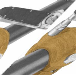
Place each half of the Roughneck coupling over the gasket, making sure
that the tongue on one housing half is aligned with the recess on the
other housing half. See Image 3.
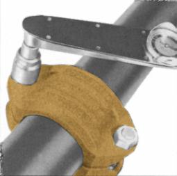
6
Tighten the nuts alternately and uniformly until the required bolt
torque is reached. See Image 4 and chart for bolt torque.
7
Reinstallation after a disassembly will require that the threads on the
bolt and in the nut are clean and lubricated with a light oil.
NOTE:
Torque requirements must be met and housing halves must be
assembled with equal gaps between bolt pads.
Working pressure and end load are based on a properly assembled
Roughneck coupling with bolts fully torqued to the above specifcations,
on plain-end or beveled standard wall steel pipe and Gruvlok Plain-End
Fittings.
Roughneck Couplings are designed to be used on plain-end pipe and
Gruvlok Plain-End Fittings only. For externally coated pipe applications,
contact Gruvlok.
Not recommended for use on steel pipe with a hardness greater than 150
Brinell, plastic, HDPE, cast iron or other brittle pipe.
*Bolt torque ratings shown must be applied at installation.
Image 1
Image 2
Image 3
Image 4
Housing
Gasket
Pipe
Grippers
Pipe
Size
Distance
from pipe
end mark
Bolt Torque
Min.
Max
In./DN(mm)
In./mm Ft.-Lbs./N-m Ft.-Lbs./N-m
2 - 2
1
/
2
1
150 190
50-65
25.4
203
257
3 - 4
1
200 250
80-100
25.4
271
339
5 - 8
1
1
/
4
250 300
125-200
31.8
339
406
10
1
3
/
4
500 600
250
44.5
678
814
12
1
3
/
4
550 700
300
44.5
746
949
14 - 16 1
3
/
4
550 700
350-400
44.5
746
949
GL-2.10
Powered by FlippingBook Publisher