Page 165 - publication
SEO Version


gruvlok installation and assembly
Introduction
Couplings
Outlets
Fittings
Val
ves &
Accesso
ries
High
Pressure
Advanced Copper
Method (IPS)
DI-LOK
®
Nipples
Plain-End
Fittings
HDPE
Couplings
Sock-It
®
Fittings
Stainless
Steel Method
Roll
Groovers
Installation
& Assembly
Special
Coatings
Design
Services
Technical
Data
Master Format
3 Part Specs.
Pictorial
Index
CTS Copper
System
www.anvilintl.com
165
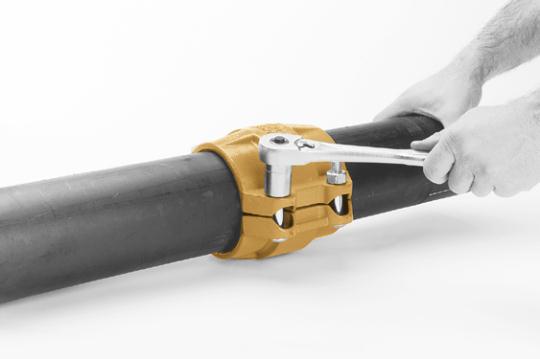
FIG. 7305
HDPE Coupling
1
Make certain the pipe ends are free of
indentations, projections or other
imperfections, which could prevent proper
sealing of the gasket. Mark each pipe at a
distance from the end of the pipe according to
the pipe size:
Size Inches
Distance to Mark
2-4" (51 - 102 mm)
1" (25.4 mm)
5-8" (127 - 203 mm)
1
1
/
4
" (31.8 mm)
10 & 12" (254 - 305 mm)
1
3
/
4
" (44.5 mm)
NOTE: Make certain the HDPE pipe end is square
cut to
1
/
8
" maximum for the 2" to 4" and
5
/
32
"
maximum for the 6" and larger sizes.
2
Check to assure the gasket material is
acceptable for the intended service. The
Gasket color code is green for EPDM and
orange for Nitrile (Buna-N).
CAUTION:
Use
only Gruvlok Xtreme
TM
Lubricant. Gruvlok
Xtreme
TM
Lubricant contains silicone. If silicone
is unacceptable for the application contact
Gruvlok for the lubrication recommendation.
Apply a thin coating of Gruvlok Xtreme
TM
Lubricant to the gasket lip and outside surface
of the gasket.
3
Slip the gasket over one of the pipe ends.
Make sure the gasket does not overhang
the pipe end. Align the second pipe and while
keeping the pipes in the butted position slide
the gasket back over the second pipe end. The
gasket must be positioned centrally between
the lines on the pipe ends.
4
Place the Figure 7305 housing casting over
the gasket, making sure the tongue on one
casting is aligned with the recess of the other
casting.
5
Insert the bolts and secure the nuts
alternately and uniformly until the bolt
pads are in contact. Torque all bolts to the
required bolt torque levels. Refer to the
Specifed Bolt Torque Table. There is no gap
between the bolt pads and the bolt torque
should be within the range given when the
coupling is properly assembled. Alternate and
even tightening of the bolts will signifcantly
reduce the torque needed to close the gap at
the pipe joint.
SPECIFIED BOLT TORQUE
Specifed bolt torque is for the oval neck track
bolts used on Gruvlok®couplings. The nuts must
be tightened alternately and evenly until fully
tightened. Caution: Use of an impact wrench is
not recommended because the torque output
can vary signifcantly due to many variables
including air pressure supply, battery strength
and operational variations.
CAUTION:
Proper torquing of coupling bolts is required to
obtain specifed performance.
Over torquing the bolts may
result in damage to the bolt and/or casting which could
result in pipe joint separation.
Under torquing the bolts may
result in lower pressure retention capabilities, lower bend
load capabilities, joint leakage and pipe joint separation.
Pipe joint separation may result in signifcant property
damage and serious injury.
FIG. 7305 SPECIFIED BOLT TORQUE
Coupling Bolts
Minimum Maximum
In.
Ft.-Lbs./N-m
Ft.-Lbs./N-m
1
/
2
X
2
3
/
8
80
100
110
150
1
/
2
X
3
80
100
110
150
5
/
8
X
3
1
/
2
100
130
135
175
3
/
4
X
4
3
/
4
130
180
175
245
GL-2.10
Powered by FlippingBook Publisher