Page 167 - publication
SEO Version


gruvlok installation and assembly
Introduction
Couplings
Outlets
Fittings
Val
ves &
Accesso
ries
High
Pressure
Advanced Copper
Method (IPS)
DI-LOK
®
Nipples
Plain-End
Fittings
HDPE
Couplings
Sock-It
®
Fittings
Stainless
Steel Method
Roll
Groovers
Installation
& Assembly
Special
Coatings
Design
Services
Technical
Data
Master Format
3 Part Specs.
Pictorial
Index
CTS Copper
System
www.anvilintl.com
167
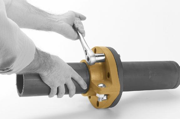
FIG. 7312
HDPE Flange Adapter
1
Make certain the pipe end is square cut to
1
/
8
" maximum for the 4" and
5
/
32
" maximum
for the 6" and 8" sizes. Inspect the surface of the
mating fange to be assured the surface is free of
dimensions of the mating fange to be assured
that the scratches, indentations, projections,
or other imperfections, which could prevent
proper sealing of the gasket.
2
Check to assure the gasket material is
acceptable for the intended service. The
gasket color code is green for EPDM and
orange for Nitrile (Buna-N).
CAUTION:
Use
only Gruvlok Xtreme
TM
Lubricant. Gruvlok
Xtreme
TM
Lubricant contains silicone. If Silicone
is unacceptable for the application contact
Gruvlok for the lubrication recommendation.
Apply a thin coating of Gruvlok Xtreme
TM
Lubricant to the gasket lips and outside surface
of the gasket.
3
Place the housing over the end of the pipe
and using a straight edge, align the face and
the fange face with the end of the pipe. Do not
let the pipe extend beyond the fange face.
4
Tighten the housing nut until the housing
bolt pads make frm metal to metal contact.
Torque all bolts to the required latch bolt
torque levels. Refer to the Specifed Latch Bolt
Torque Table.
5
Position the Gruvlok Flange gasket around
the pipe end and press the gasket into the
fange gasket pocket. Be sure the fange sealing
lips are facing out.
6
Align the Gruvlok Flange bolt holes with
the mating fange bolt holes. Insert a
standard bolt or stud through one bolt hole and
thread the nut on hand tight. Insert the next
bolt or stud opposite the frst and thread the
nut on hand tight. Continue this procedure until
all holes have been ftted. Note: Take care to
assure the gasket lip is not bent backwards and
pinched between the two fanges.
7
Tighten the fange face nuts alternately
and evenly so that the fange faces remain
parallel and make frm contact around the entire
fange. Torque all bolts to the required mating
fange joint torque levels. Refer to the Specifed
Mating Flange Bolt Torque Table.
SPECIFIED BOLT TORQUE FOR LATCH
& MATING FLANGE BOLTS
Specifed bolt torque is for the latch and mating
fange bolts used on Gruvlok®fanges. The
nuts must be tightened alternately and evenly
until fully tightened.
CAUTION:
Use of an
impact wrench is not recommended because
the torque output can vary signifcantly due to
many variables including air pressure supply,
battery strength and operational variations.
CAUTION:
Proper torquing of latch and mating
fange bolts is required to obtain specifed performance.
Over torquing the bolts may result in damage to the bolt
and/or casting which could result in pipe joint separation.
Under torquing the bolts may result in lower pressure
retention capabilities, lower bend load capabilities, joint
leakage and pipe joint separation. Pipe joint separation may
result in signifcant property damage and serious injury.
FIG. 7312 LATCH BOLT TORQUE
Latch Bolts
Minimum Maximum
In.
Ft.-Lbs./N-m Ft.-Lbs./N-m
5
/
8
X
1
5
/
8
100
130
135
175
3
/
4
X
2
130
180
175
245
FIG. 7312 MATING FLANGE BOLT TORQUE
Mating Flange Bolts Minimum Maximum
In.
Ft.-Lbs./N-m Ft.-Lbs./N-m
5
/
8
X
3
110
140
149
190
3
/
4
X
3
1
/
2
220
250
298
339
GL-2.10
Powered by FlippingBook Publisher