Page 169 - publication
SEO Version


gruvlok installation and assembly
Introduction
Couplings
Outlets
Fittings
Val
ves &
Accesso
ries
High
Pressure
Advanced Copper
Method (IPS)
DI-LOK
®
Nipples
Plain-End
Fittings
HDPE
Couplings
Sock-It
®
Fittings
Stainless
Steel Method
Roll
Groovers
Installation
& Assembly
Special
Coatings
Design
Services
Technical
Data
Master Format
3 Part Specs.
Pictorial
Index
CTS Copper
System
www.anvilintl.com
169
FTV-S (Straight) & FTV-A (Angle Body)
Tri-Service Valve
INSTALLATION:
1
The valve should be mounted to a spool piece on the discharge
side of the pump. Spool piece required is based on a minimum
recommended space of 12" for pump sizes 2" x 2" to 6" x 6" and 24" for
pump sizes 8" x 8" to 12" x 12".
2
It is not recommended to mount a valve directly to the pump as
this could cause undesirable noise in the system.
3
Suffcient clearance around the valve should be left for valve
removal or repair.
4
Install valve in the direction of the fow arrows on the valve body.
5
The valve can be mounted to fanged equipment using Gruvlok
Flange Adapter or industry standard grooved coupling, suitable for
system pressure and temperatures encountered.
6
The Gruvlok Tri-Service valve bodies have anti-rotation lugs on the
inlet and outlet. These lugs, combined with the Flange Adapters,
provide a ridged rotation free installation.
7
The valve body has been designed to handle the weight of the
pump on vertical in-line installations. The body is not designed to
support the piping weight. It is recommended that the piping be
supported by hangers. Pipe supports should be provided under the
valve and strainer bodies.
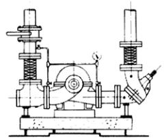
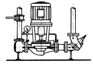
TYPICAL INSTALLATIONS
Base-Mounted Single Suction
Base-Mounted Double Suction
Vertical In-Line
LEGEND
Gruvlok ductile iron flange
adapters for ANSI 150# flanges
Gruvlok ductile iron flange
adapters for ANSI 300# flanges
Grooved end with 375 psi rated
pipe coupling
A
A
B
C
Temperature
°
C
Temperature
°
F
Note: for temperatures between 230
°
F and 300
°
F
(110
°
C and 149
°
C) specify Viton Elastomers.
Pressure (psi)
Pressure (kpa)
400
-46
°
-29
°
-18
°
10
°
38
°
66
°
93
°
110
°
-50
°
-20
°
-0
°
50
°
100
°
150
°
200
°
230
°
375
300
250
200
100
0
2,760
2,585
2,070
1,724
1,380
690
250
B & C
PRESSURE – TEMPERATURE LIMITS
FIELD CONVERSION
(Straight to Angle Pattern Valve)
1
Open valve at least one complete turn,
2
Remove the body bolts from valve body
using Allen Key.
3
Rotate one half of the valve body 180°
making sure the lower valve seat and “O”
Ring stay in position. Inspect the “O” Ring for
any cuts or nicks and replace if necessary.
4
Replace body bolts and torque evenly to
70 ft./lbs.
FLOW MEASUREMENT
Where approximate indication of fow is acceptable the Gruvlok Tri-Service valve can be used.
FLOW MEASUREMENT VALVE IN WIDE OPEN POSITION
Measure and record the differential pressure across the valve using a Flow Meter with high
pressure range transducer or pressure gauges with PMP adapters.
Refer to Tri-Service Performance Curves with valve in full open position (See Determining Flow
Rate with Valve in Throttled Position Section on page 165). Locate Pressure Differential on left
hand side of chart and extend line horizontally across to valve size being used. Drop line
vertically down and read fow rate from bottom of chart.
CAUTION
:
Safety glasses should be used and the probe should
not be left inserted into fttings for prolonged periods
of time (overnight, etc.), as leakage from the PMP may
occur when probe is removed.
GL-2.10
Powered by FlippingBook Publisher