Page 170 - publication
SEO Version


gruvlok installation and assembly
www.anvilintl.com
170
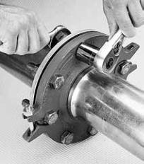
5
The correct positioning and
relationship of all components
comprising a Gruvlok Flange joint. The
Fig. 7012 Gruvlok Flange gasket must be
inserted so that the sealing lips face
toward the tube end and the mating
fange face and away from the Gruvlok
Flange itself.
NOTE: Design of the Gruvlok Flange
provides sealing only with the special
Gruvlok Flange gasket. Only Gruvlok
Flange gaskets may be used with Fig.
7012 Gruvlok Flanges.
Proper position
of gasket
sealing lips
Gasket
Flange,
pump,
tank,
valve,
etc.
Gruvlok
Flange
Grooved
Pipe
FLANGE ADAPTER INSTALLATION:
1
The Fig. 7012 Gruvlok Flange Adapter
can be used with the FTV Tri-Service
Valve. Installation is similar to the
installation of the Figure 7012 with
grooved pipe.
FTV-S (Straight) & FTV-A (Angle Body)
Tri-Service Valve
2
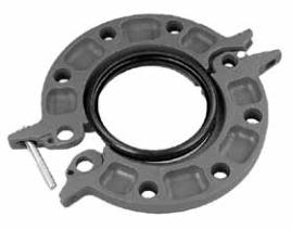
Loosen the nut on the latch bolt to the
end of the bolt thread. (It is not
necessary to remove the nut from the
latch bolt.) Swing the latch bolt out of the
slot. Open the Gruvlok Flange and place it
around the grooved tube with the key
section ftting into the groove. The fange
gasket cavity must face the tube end.
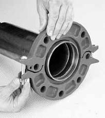
3
Swing the latch bolt back into the
slotted hole. Tighten the nut until the
fange halves make solid contact.
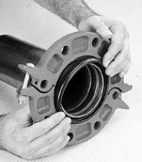
4
Check the gasket grade to verify that it
is properly suited for the intended
service. Lubricate the entire surface of the
gasket and the fange gasket cavity using
Gruvlok lubricant. Position the Gruvlok
Flange Gasket around the tube end and
press the gasket into the cavity between
the tube O.D. and the fange recess. The
gasket must be properly positioned as
shown in Step 5. Be careful that foreign
particles do not adhere to lubricated
surfaces.
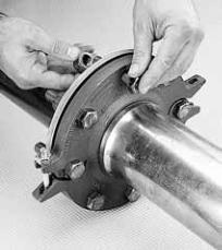
6
Align the Gruvlok Flange bolt holes
with the mating fange bolt holes.
Insert a standard bolt or stud through the
bolt hole, and thread a nut on hand tight.
Insert the next bolt or stud opposite the
frst and again thread the nut on hand
tight. Continue this procedure until all
holes have been ftted. (See illustration)
NOTE: Take care to assure that the gasket
lip is not bent backwards or pinched
between the two fanges.
7
Tighten the nuts evenly so that the
fange faces remain parallel and make
frm even contact around the entire
fange. Torque all bolts to required fange
joint torque levels.
1
START
Recommended Bolt Tightening Sequence
16
11
8
3
13
10
5
2
7
4
14
9
6
15
12
GL-2.10
Powered by FlippingBook Publisher