Page 171 - publication
SEO Version


gruvlok installation and assembly
Introduction
Couplings
Outlets
Fittings
Val
ves &
Accesso
ries
High
Pressure
Advanced Copper
Method (IPS)
DI-LOK
®
Nipples
Plain-End
Fittings
HDPE
Couplings
Sock-It
®
Fittings
Stainless
Steel Method
Roll
Groovers
Installation
& Assembly
Special
Coatings
Design
Services
Technical
Data
Master Format
3 Part Specs.
Pictorial
Index
CTS Copper
System
www.anvilintl.com
171
FTV-S (Straight) & FTV-A (Angle Body)
Tri-Service Valve
0
0
20
2.0
5.0
50
3.0
.5
1
3
5
5.0 10 20
50 100 200 400
FLOWRATE (L/SEC)
PRESSURE DROP (FT. WG)
FLOWRATE (US GAL/MIN)
100
500 1000 2000 4000 6000
10
20
2.0
5.0
10
20
20
40
40
60
60
80
12"
6"
2"
2
1
/
2
"
6"
5"
8"
10"
3"
4"
2
1
/
2
"
80
100
100
PERCENT OF FULL OPEN
Inherent Flow Characteristic Curve
with Valve in Throttled Position
Tri-Service Performance Curve
with Valve in Full Open Position
PERCENT OF MA
X FLOW
4"
5"
8"
10"
12"
DETERMINING FLOW RATE WITH VALVE IN THROTTLED POSITION:
1
Record the size of valve and stem position using the Flow Indicator
Scale (See Flow Indicator Section at bottom of page). Calculate
percentage of valve opening referring to table below:
2
Measure and record the differential pressure across the valve in the
throttled position.
3
Locate percentage of valve opening on the bottom scale of Flow
Characteristic Curve. Project line vertically up to intersect with the
Valve Characteristic Curve and from this point project line horizontally
across to the left of the chart and record the percentage of maximum
fow rate.
4
On the Tri-Service Performance Curve locate the differential
pressure obtained in Step 2 and project line horizontally across to
intercept with Valve Performance Curve. Drop a line vertically down to
read the fow rate at the bottom of the chart.
VALVE SIZE 2
1
/
2
3
4 5
6 8 10 12
Number of Rings
(valve full open)
5
5
6
9 10 12 18 28
5
To calculate fow rate of valve in th throttled position, multiply
the fow rate from Step 4 by the percentage fow rate from Step 2
divided by 100.
Example:
Valve size 4 in.
Differential Pressure in 5.4 ft. (1.65 m)
Number of rings open 3, (3 rings / 6 rings X 100) = 50% throttle
Solution:
• From the Tri-Service Performance Curve (fg. 5), a 4 in.
valve with 5.4 ft. pressure drop (1.65 m) represents a fow
of 400 USgpm (25.2 L/s).
• From Flow Characteristic Curve (fg, 6), a 4 in. valve, 50%
open, represents 34% of maximum fow.
• Approximate fow of a 4 in. valve, with a 5.4 ft. ( 1.65 m)
pressure drop when 50% throttled is:
(400 x 34)/100 = 136 USgpm
(25.2 x 34)/100 = 8.57 L/sec.
Note:
To prevent premature valve failure it is not recommended
that the valve operate in the throttled position with more
than 25 ft. pressure differential. Instead the pump impeller
should be trimmed or valves located elsewhere in the
system to partially throttle the fow.
2.0
5.0
50
3.0
.5
1
3
5
5.0 10 20
50 100 200 400
FLOWRATE (L/SEC)
PRESSURE DROP (MH
2
O)
PRESSURE DROP (FT. WG)
FLOWRATE (US GAL/MIN)
100
500 1000 2000 4000 6000
10
20
2.0
5.0
10
20
6"
2"
2
1
/
2
"
Tri-Service Performance Curve
with Valve in Full Open Position
PERCENT OF MAX FLOW
4"
5"
8"
10"
12"
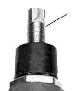
FLOW INDICATOR SCALE
The valve stem with its grooved rings and positioning sleeve indicates the throttled position of the
valve. The quarter turn graduations on the sleeve, with the scribed line on the stem, provide for
approximate fow measurement.
Note: The valve is shipped in the closed position. The indicator on the plastic sleeve is aligned with
the vertical scribed line on the stem.
Scribed Lines
GL-2.10
Powered by FlippingBook Publisher