Page 90 - publication
SEO Version


valves and accessories
www.anvilintl.com
90
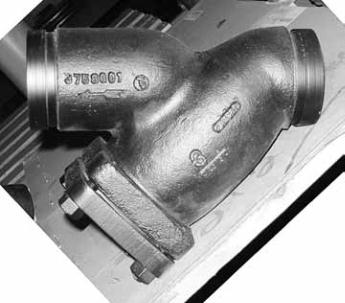
FIGURE 758 G GROOVED-END “WYE” STRAINER
Nominal
Size
O.D.
Dimensions
Approx. Wt.
Each
A
B
C
Plug Size
D
In./DN(mm)
In./mm In./mm In./mm In./mm In./mm
Lbs./Kg
2
2.375
7
7
/
8
5
1
/
4
1
/
2
7
12.0
50
60.3
200
133
25
178
5.4
2
1
/
2
2.875
10
6
1
/
2
1
9
3
/
4
18.0
65
73.0
254
165
25
248
8.2
3
3.500
10
1
/
8
7
1
10
23.0
80
88.9
257
178
25
254
10.4
4
4.500
12
1
/
8
8
1
/
4
1
1
/
2
12
42.0
100
114.3
308
210
38
305
19.1
5
5.563
15
5
/
8
11
1
/
4
2
17
80.0
125
141.3
396
286
51
432
36.3
6
6.625
18
1
/
2
13
1
/
2
2
20
112.0
150
168.3
470
343
51
508
50.8
8
8.625
21
5
/
8
15
1
/
2
2
22
3
/
4
205.0
200
219.1
549
394
51
577
93.0
10
10.750 25
3
/
4
18
1
/
2
2
28
277.0
250
273.1
654
470
51
711
125.6
12
12.750
30
21
3
/
4
2
30
470.0
300
323.9
762
552
51
762
213.2
MODEL 758G
Grooved-End “Wye” Strainer
SERVICE RECOMMENDATIONS
For use in water, oil & gas piping to provide economical protection for
pumps, meters, valves, compressors, traps & similar equipment.
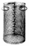
SCREENS
Standard screens for Y-Strainer are perforated 304 Stainless Steel with spot
welded seam. Mesh lining is available in all alloys for extra fne straining.
Recommended standard perforations are listed below in the material
specifcations.
GRUVLOK STRAINER BASKET
Furnished as standard in sizes 8" (43 mm) and larger.
A one-quarter turn securely locks the screen in its seat
and frees the serviceman for securing the cover fange
to the body of the strainer.
Contact a Gruvlok Rep. for other applications.
CONSTRUCTION
All covers have an NPT
blowoff outlet at location
“C”. Recessed seat in the cover
ensures accurate screen alignment.
Bosses at the inlet and outlet fanges
are provided for gauge taps.
Self-cleaning is done by opening the valve or plug connected to the
blowoff outlet. (Advise when strainers are to be mounted in vertical piping,
so we can rotate the cover to position the blowoff at the lowest point.)
BLOWOFF OUTLETS
Tapped NPT size specifed in the dimension table. Blowoff outlets are not
normally furnished with plugs.
INDIVIDUALLY HYDROSTATICALLY TESTED
Working Pressures Non-Shock
640 PSI @ 150°F (45 Bar @ 65°C)
Flow data:
NOTE 1.
Most U.S. piping engineers specify system startup instructions for new systems which
include removing the pre-flter screen after system fushing of the main piping before the
system is put into normal operation. Flow data values are based on fow of clean water at
ambient temperatures. The pressure drop across the diffuser basket strainer, 50% clogged,
is approximately twice as great as that of a clean strainer.
NOTE 2.
Suction Diffuser baskets need a routine maintanence program to maintain system
effciency.
material specifications
BODY & COVER:
Ductile Iron ASTM A 395 Grade 60-40-18
FLAT GASKETS:
Non-asbestos
SCREEN:
2" - 4" Type 304 Stainless Steel
1
/
16
" (1.6mm) dia. holes
5" - 12" Type 304 Stainless Steel
1
/
8
" (3.2mm) dia. holes.
COUPLING:
Ductile iron ASTM A 536 Grade 65-45-12
*Maximum working pressure is based upon the performance capability of the Gruvlok
®
Strainer.
Maximum system working pressure is dependant upon the couplings used for installation and the
pressure capacity of other system components.
Not for use with copper systems.
.1
2
3
4
5
6
7
8
9
2
3
4
5
6
7
8
9
10
2 3 4 5 6 7 8 9
10
1
1
/
2
2
1
/
2
2
3
4 5 6 8 10 12
Cv
PORD ERUSSERP
.i.s.p -
FLOW RATE - g.p.m.
GROOVED END “Y” TYPE STRAINERS
SIZE (inches)
100
2 3 4 5 6 7 8 9 1000 2 3 4 5 6 7
1.0
B
C
(NPT)
D
Screen
Removal
A
GL-2.10
Powered by FlippingBook Publisher