


 106 / 114

SECTION
SUBSECTION
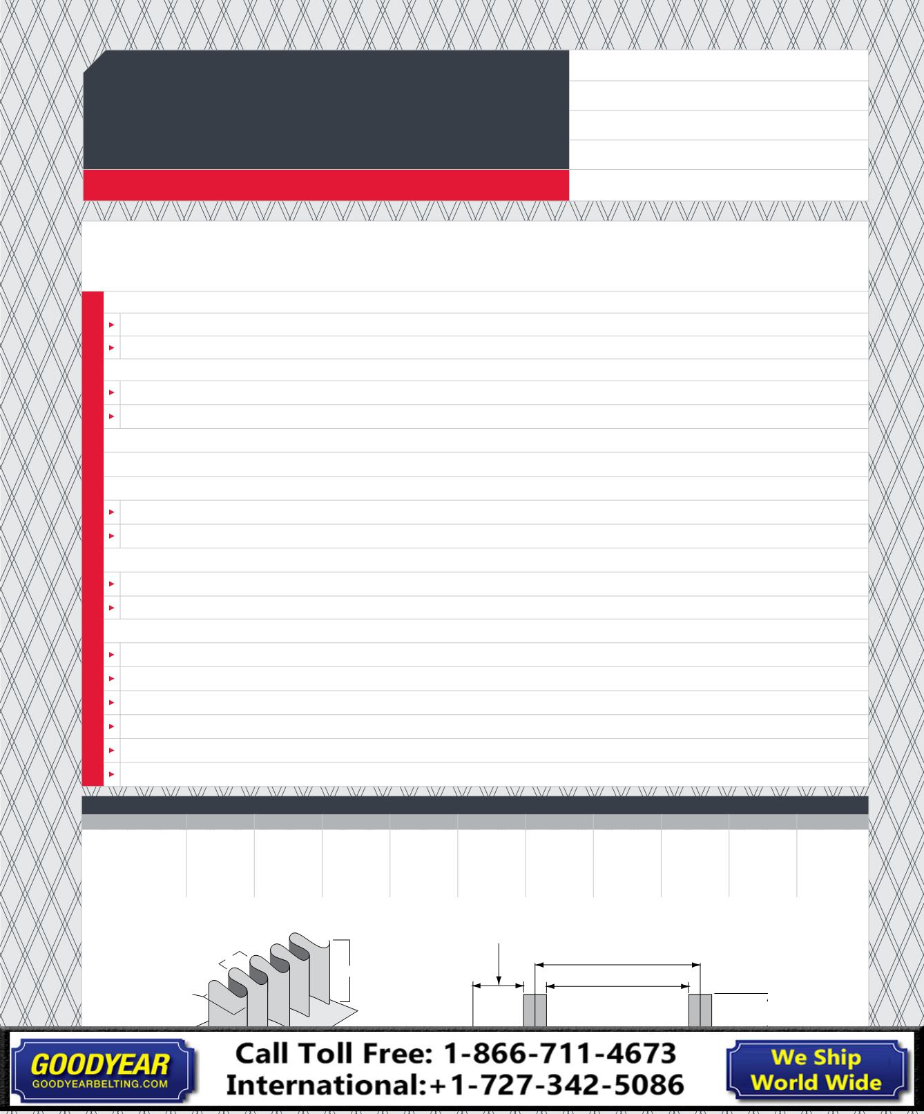
DUROWALL™ DIMENSIONS
MM
INCH
MM
INCH
MM
INCH
MM
INCH
MM
INCH
HEIGHT “H”
30
1-1/4
40
1-1/2
50
2
60
2-3/8 80
3-1/8
BASE WIDTH “B”
30
1-3/16 30
1-3/16 60
2-3/8 60
2-3/8 60
2-3/8
WALL WIDTH “W”
19
3/4
19
3/4
40
1-1/2
40
1-1/2
40
1-1/2
PITCH “P”
22
7/8
22
7/8
40
1-9/16 40
1-9/16 40
1-9/16
W
To ensure your belt is manufactured with a proper sidewall specification, please refer to the below diagrams and complete
the following:
BELT STYLE
Part number:
Description:
BELT LENGTH AND WIDTH:
Length:
Width (see illustration, #1):
MINIMUM PULLEY DIAMETER:
SIZE OF SIDEWALL (#2):
PLEASE NOTE PLACEMENT OF SIDEWALL:
Flush with edge of belt:
Indent from belt edge to corrugation (#3):
INSIDE SPACE BETWEEN SIDEWALL:
Center to center of sidewall (#4):
Inside corrugation to inside corrugation (#5):
NOTE PLACEMENT OF CLEATS (IF APPLICABLE):
Cleat height:
Cleat spacing:
Cleat width:
Style: T-cleat, scoop, lug:
Flush to foot of wall / flush to corrugation / indent from sidewall cleat?
Additional sidewall to be left loose for field joining?
P
W
H
B
Belt Width #1
Belt Edge to Sidewall #3
Center to Center Sidewall #4
Inside Sidewall #5
Height
of
Sidewall #2
NAME:
COMPANY:
PHONE #:
EMAIL:
DATE:
LIGHTWEIGHT DUROWALL
™
DESIGN WORKSHEET
Here’s what we need from you.